Surface Optimization
Surface optimization is carried out in Shaper.
Surface optimization adds, corrects or perfects surface information after importing.
Triangulation
Patchwork 3D Design uses a powerful geometry engine that enables it to preserve the geometrical information of each surface.
When a surface is derived from a parametric definition (for example, a NURBS), it is possible to modify its degree of tessellation, that is, the resolution of the triangular mesh that makes up the surface. This allows you to optimize the ratio of the rendering quality relative to the number of triangles generated.
Patchwork 3D Design will also tessellate groups of surfaces. Interactive tessellation is possible for the applicable surface, no matter what types of surfaces make up the mixed selection.
Surface tessellation can be modified
| Icon | Function | Description |
|---|---|---|
|
|
Increase Triangulation | Increases the tessellation of a surface by one degree (refine the surface by increasing the number of triangles). |
|
|
Decrease Triangulation | Reduces the tessellation of a surface by one degree. |
|
|
Set Triangulation | Sets and imposes a specific level of tessellation. |
|
|
Set Advanced Triangulation | Gives access to the advanced triangulation settings. |
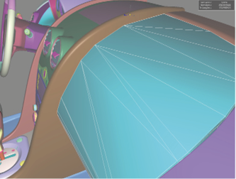
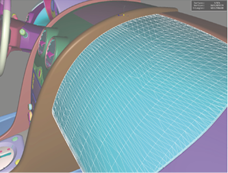
Figure 81 : Modification of the tessellation parameter on a parametric surface.
-
 Convert to Mesh: deletes the parametric representation of the selected surfaces. The current tessellation is permanently affected to the surface. This reduces the space taken up by surfaces in the database.
Stitch and Split Functions
In the Surface > Surface Topology menu:
Orientation: Front and Back Faces
A surface is an oriented geometrical element with a front side and a rear side. By default, the back faces of surfaces are culled, that is, not displayed. In Shaper, culled backfaces are displayed in red.
Two visualization options are available in the Viewport menu:
| Icon | Function | Description |
|---|---|---|
|
|
Track culling | Renders culled backfaces in red, making it possible to tell which faces aren't displayed. This option is enabled by default. |
|
|
Backface culling | Optimizes rendering by not calculating the back of surfaces, substantially accelerates the calculation of interactive 3D images. This option is enabled by default. |
To use backface culling correctly, the front face of the surfaces needs to be oriented to the visible side of the delimited volume. You can modify the orientation of the surface front and back faces from the Surface menu:
|
Figure 82 : The incorrectly oriented surfaces are selected... |
Figure 83 : ... and then inverted. |
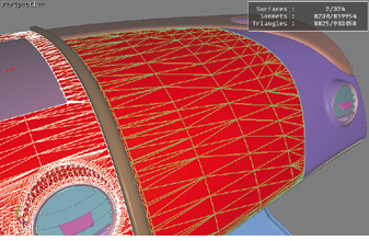
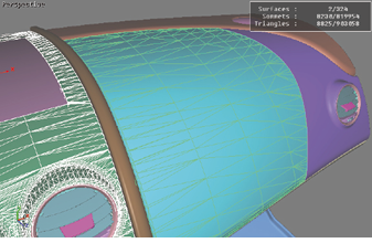
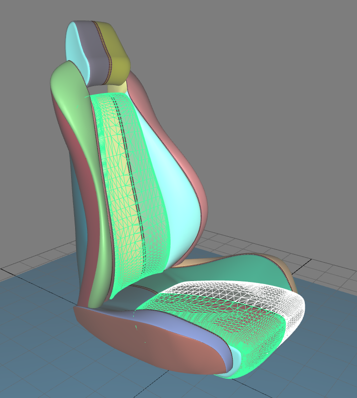
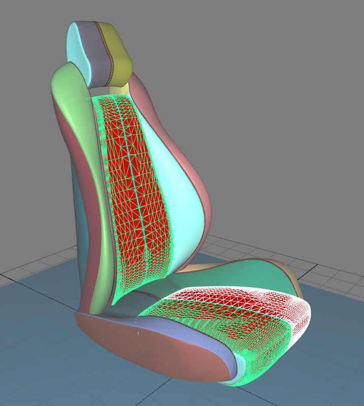
Figure 84 : Example of the Reverse function (initial orientation on the left, final orientation on the right).
